Networking & Content Delivery
Design and build IPv6 internet inspection architectures on AWS
As organizations increasingly adopt IPv6 to address public IPv4 exhaustion, private IPv4 scarcity—especially in large-scale networks—and the need to support IPv6-only clients, securing both IPv4 and IPv6 traffic becomes critical. We can apply consistent traffic inspection for inbound and outbound flows in Amazon Virtual Private Clouds (Amazon VPCs) to maintain security. In this post, we explore best practices and reference architectures for implementing internet egress inspection for IPv6 traffic in Amazon VPCs. This is achieved using Amazon Web Services (AWS) Network Firewall and AWS Gateway Load Balancer (GWLB) with third-party firewall appliances.
AWS offers two main approaches for deploying IPv6: dual stack and IPv6-only. In a dual stack setup, workloads operate with both IPv4 and IPv6 addresses, whereas in an IPv6-only deployment, workloads use only IPv6 addresses. The two IP stacks function independently; thus, we focus in this post on best practices and design considerations specific to IPv6.
Prerequisites
We assume that you are familiar with fundamental networking constructs on AWS: for example Amazon VPCs, Internet Gateway (IGW), Subnets, route tables, Network Firewall, and GWLB. We won’t focus on defining these services, but we do outline their capabilities as they relate to designing and building IPv6 internet egress inspection architectures on AWS.
IPv6 internet connectivity on AWS
In a dual stack Amazon VPC, we maintain the same internet connectivity constructs for the IPv4 stack, while we add the Egress-only Internet Gateway (EIGW) for the IPv6 stack. Although public subnets in IPv6 have bidirectional internet connectivity through the IGW, private subnets in IPv6 use an EIGW for internet connectivity. An egress-only IGW is a horizontally scalable, redundant, and highly available VPC component that only allows outbound IPv6 communication from resources in your VPC. The role of the EIGW is to keep the concept of private subnets consistent across both IPv4 and IPv6 stacks. The EIGW prevents internet endpoints from initiating IPv6 connections to your instances in private IPv6 subnets. The following diagram shows IPv6 internet connectivity for private and public subnets in a VPC:

Figure 1: Amazon VPC IPv4 and IPv6 internet connectivity
- Resources in private IPv4 or dual stack subnets in the VPC use the AWS NAT Gateway to egress to internet IPv4 endpoints. The NAT Gateway translates the source IPv4 address of packets, and sends traffic to the internet through the IGW.
- Resources in public IPv4 or dual stack subnets use Elastic IPv4 addresses for bidirectional communication with internet IPv4 endpoints through the IGW. Traffic can be initiated both from resources in the VPC and from internet resources.
- Resources in public IPv6 or dual stack subnets use their IPv6 addresses in the VPC to bidirectionally communicate with internet IPv6 endpoints through the IGW. Traffic can be initiated both from resources in the VPC and from internet resources.
- Resources in private IPv6 or dual stack subnets use their IPv6 addresses in the VPC to communicate with internet IPv6 endpoints, through the Egress-only IGW. Traffic can be initiated only from resources in the VPC.
Inspection patterns for IPv6 traffic on AWS
In IPv6, internet traffic from a VPC can be locally inspected using both Network Firewall and GWLB with third-party appliances. We distinguish two main patterns for inspecting IPv6 internet traffic on AWS:
Distributed egress and ingress IPv6 internet traffic inspection
In a distributed design, you deploy Network Firewall or GWLB endpoints in each VPC, and use the VPC-local IGW for internet access. Subnets needing traffic inspection route outbound traffic through these endpoints. For return or inbound internet traffic, the IGW route table makes sure of symmetric routing through the firewall or load balancer endpoints within each Availability Zone (AZ). For subnets that should not allow internet inbound traffic, your firewall policy must deny any internet originated traffic, and allow only the return flows. The following figure shows two versions of high-level VPC routing for distributed internet traffic inspection: the left diagram is using GWLB and appliances, the right is using Network Firewall:

Figure 2: Distributed internet traffic inspection—ingress and egress
Egress internet traffic from the resources within the VPCs is sent toward the Network Firewall or GWLB endpoint located in the same AZ. Ingress traffic flows through the firewall endpoints, following the configuration of the IGW associated edge route table.
Centralized ingress IPv6 internet traffic inspection
For centralized ingress, you need to use AWS Transit Gateway or AWS Cloud WAN to route between your central ingress VPC and the internal VPCs. The ingress elastic load balancers you deploy act as proxies and perform the address translation. Therefore, you can use either Network Firewall or GWLB with third-party appliances for traffic inspection. For details on inspection architectures using Network Firewall, we recommend reading IPv6 deployment models for AWS Network Firewall.
Centralized egress IPv6 internet traffic inspection
There are two options for centralizing egress IPv6 traffic inspection:
- Deploying distributed GWLB endpoints in each spoke VPC: you can deploy GWLB endpoints in each of your VPCs and centralize egress in the VPC containing your GWLB and firewall appliances, as shown in the following figure. This option allows you to optimize data processing costs by removing the need to route traffic through Transit Gateway or AWS Cloud WAN. This option only works as egress-only and can’t accept new flows from the appliance side. Furthermore, you can’t create the load balancer in IPv6-only subnets.
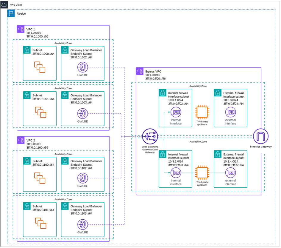
Figure 3: Centralized egress internet traffic inspection with distributed endpoints
- Using Transit Gateway or AWS Cloud WAN to route egress traffic to a centralized egress VPC that contains the GWLB, GWLB endpoints, and third-party firewall appliances, as shown in the following figure. For details on configuring centralized egress with Transit Gateway, check Centralized inspection architecture with AWS Gateway Load Balancer and AWS Transit Gateway.

Figure 4: Centralized egress traffic inspection with Transit Gateway or AWS Cloud WAN
In this post we focus on the first option, using distributed GWLB endpoints. This design allows traffic to be redirected locally within each VPC to the centralized inspection appliances, avoiding the need to route through a Transit Gateway. It streamlines routing, enables better fault isolation, and improves scalability by distributing the inspection entry points.
Considerations for third-party appliances centralized egress
The following are design considerations for centralized IPv6 egress internet traffic inspection using GWLB endpoints and third-party appliances:
- Support for NAT66 or NPTv6: Make sure that the third-party inspection appliances used in the architecture support IPv6 address translation. IPv6 prefixes are local to their VPC where you assign them, thus IPv6 addresses must be translated in the centralized VPC for egress traffic. Therefore, your third-party appliances must support NAT66 (Stateful, IPv6-to-IPv6 Network Address Translation) or NPTv6 (Stateless, one-to-one IPv6 prefix translation). This architecture is currently not applicable for Network Firewall, since it doesn’t support NAT66/NPTv6. This architecture also allows you to provide internet egress connectivity for resources addressed using GUA, IPv6 ULA, or private GUA IPv6 addresses.
- Support for two-arm mode: Confirm that your chosen inspection device is capable of operating in two-arm mode, allowing it to handle traffic through both ingress and egress interfaces. This is necessary since the appliances perform NAT66 / NPTv6. Refer to the Best practices for deploying Gateway Load Balancer to learn more about the two-arm mode.
- Supports GENEVE protocol: Make sure that your inspection appliance supports the Generic Network Virtualization Encapsulation (GENEVE) protocol (UDP port 6081) used by GWLBs, can interpret GENEVE metadata, and can respond to GWLB health checks.
Traffic flows for centralized egress internet traffic inspection with distributed endpoints
Traffic flow from application/Amazon EC2 instance to the internet:
- Internet-bound traffic from the Amazon Elastic Compute Cloud (Amazon EC2) instance within the VPC is routed locally to the GWLB endpoint deployed within the same AZ of the VPC.
- The GWLB endpoint sends the traffic to the GWLB associated with the endpoint, which encapsulates it using the GENEVE protocol.
- Then, the GWLB forwards the GENEVE-encapsulated traffic to the security appliance on its internal firewall interface for inspection.
- After the traffic is inspected by the firewall, the device performs Network Address Translation (NAT66 or NPTv6, depending on its capabilities) and routes the GENEVE-decapsulated traffic through the external firewall interface toward the IGW for outbound transmission.
Return traffic flow from internet to the application/EC2 instance:
- The return traffic from the internet is directed from the IGW toward the firewall’s external firewall interface based on the ingress route table. The firewall performs de-NAT (reversing NAT66 or NPTv6) to restore the original private IP address of the destination EC2 instance.
- After de-NAT, the security appliance re-encapsulates the traffic using the GENEVE protocol and sends to the GWLB.
- The GWLB examines the GENEVE header, which contains metadata identifying the originating GWLB endpoint. Based on this, the GWLB returns the traffic to the same AZ and VPC where the original request came from. The GWLB sends the encapsulated packet to the GWLB endpoint located in the originating VPC and AZ. The endpoint then decapsulates the packet and forwards it locally to the EC2 instance.
- This design necessitates placing each GWLB endpoint in its own subnet to make sure that a dedicated route table can be used. This separation is critical, because it allows precise routing control for GWLB return traffic.
GWLB and GWLB endpoints configuration for dual stack operation
Step 1: Create target groups
- Go to EC2 service, under the Load Balancing section, choose Target Groups.
- Choose Create target group.
- Choose target type as Instances, as shown in the following figure.

Figure 5. Target group settings
- When creating a target group, make sure that you configure the health check correctly. Before setting up the health check protocol and port, consult the manufacturer’s recommendations for your appliance. Settings vary significantly between devices: some use the web interface port, others specify a dedicated heartbeat port, and some need entirely different protocols or ports. Following the manufacturer’s guidelines makes sure of optimal performance and accurate health checks. Incorrect settings can result in false positive or negative health checks, impacting application availability and performance. Review your appliance’s documentation thoroughly before configuring health checks.
Step 2: Deploy a GWLB
- Go to EC2 service, under the Load Balancing section, choose Load Balancers.
- Choose Create Load Balancer and choose Gateway Load Balancer.
- Under Basic configuration, choose Dualstack and add the VPC and AZs as shown in the following figure.

Figure 6. GWLB settings
- Choose the target group that you just created and choose Create load balancer.
- Wait for the GWLB to be provisioned. When the GWLB is provisioned, go to the Target Groups, choose the target group you created, and wait for the appliance instances to show healthy. If they don’t respond after 50 seconds (using default timers), then troubleshoot the health check setup and your appliances.
Step 3: Create an endpoint service
- Go to VPC service, under the Virtual private cloud section, choose Endpoint services.
- Choose Create endpoint service.
- Under the Endpoint service settings, choose Load balancer type as Gateway, and choose the GWLB you just created.
- Under Additional settings, you may choose to keep the Acceptance required box checked. However, make sure to choose both IPv4 and IPv6 under Support IP address types as shown in the following figure.

Figure 7. Endpoint service settings
- When you’re done, choose Create.
- For further details, look into the Create an endpoint service documentation.
Step 4: Create an endpoint in each spoke VPC
When the endpoint service is created, you must create one endpoint per subnet for the application to connect to. To perform this action:
- Go to VPC service, and under the Virtual private cloud section choose Endpoint.
- Follow the steps mentioned under connect to an endpoint service as the service customer to create the endpoint.
- While creating the endpoint, make sure that it is associated with the GWLB endpoint service name you just created, as shown in the following figure.

Figure 8. Endpoint VPC association
- Choose Create endpoint.
Route table configuration for spoke VPCs and egress VPC

Figure 9: Route table configurations for centralized egress internet traffic inspection with distributed endpoints
Considerations
- GWLB IPv6 behavior: GWLB supports IPv6 traffic natively. However, it does so by encapsulating traffic using the Geneve protocol (port 6081) in IPv4 packets, whether the traffic is IPv4 or IPv6. Make sure that you allow port 6081 to decapsulate and route IPv4 Geneve traffic on third-party security appliances.
- Dual-stack configuration for resources: Make sure that all relevant AWS resources (for example EC2 instances, subnets, route tables, and load balancers) are configured for dual-stack (IPv4 and IPv6).
- Subnet and routing configuration: For security, GWLB should be used in private subnets. Make sure that your VPC is configured with dual stack subnets. This allows configuring IPv6 CIDR blocks to route IPv6 traffic. Use route tables to send IPv6 traffic to a GWLB endpoint in the VPC. Furthermore, GWLB endpoints are zonal, thus routing should be carefully orchestrated in every AZ where your ingress traffic reaches you.
- Security groups and NACLs for IPv6: Make sure that your security groups and NACLs allow Inbound IPv6 connections to the ports of interest (http/HTTPS).
- IPv6-only as opposed to dual-stack designs: Decide whether your network is IPv6-only or IPv4+IPv6 dual-stack. Choose IPv6-only architecture when building modern, cloud-native applications where you want streamlined network management and don’t need legacy IPv4 support, resulting in reduced operational overhead. Dual-stack enables IPv6 for new applications while retaining IPv4 support for legacy clients. When you’re running dual-stack configurations, consider NAT64 or other protocols when IPv6-only backends need to communicate with IPv4 resources.
- Observability and logging: You may consider monitoring IPv6 traffic flows to and from the GWLB endpoints using VPC Flow Logs. This helps identify anomalous patterns and troubleshoot connectivity issues across environments.
- Traffic logs and metrics: Amazon CloudWatch Logs and Metrics are useful to understand the traffic behavior and identify potential issues. Make sure that your third-party appliances log and monitor IPv6 traffic.
- High availability and scalability: GWLB and its endpoints have high availability by default. Nonetheless, to make sure of high uptime, run GWLB endpoints in more than one AZ and set up your route tables within each subnet to direct traffic to the AZ-local endpoint. Make sure that the virtual appliances behind the GWLB are horizontally scalable, because the GWLB is capable of processing large amounts of traffic but it depends on the appliances for its handling.
- Cost implications: Get familiar with AWS usage costs. To calculate costs per month, use AWS Pricing Calculator.
- IPv6 DNS considerations: Make sure that your Amazon Route 53 records contain AAAA records for resources receiving traffic on IPv6 addresses. This allows clients to connect directly to an IPv6 address. If your service supports both IPv4 and IPv6 clients, then add dual-stack DNS records.
Conclusion
In this post, we outlined a method for designing an egress inspection architecture with IPv6 using Gateway Load Balancers. This approach uses the capability of third-party firewall/security appliances to perform NAT66 or NPTv6, enabling customers to seamlessly migrate to IPv6 without concerns regarding egress inspection. Furthermore, the solution is cost-effective from an AWS standpoint, because it avoids the need for AWS NAT Gateway-type appliances in the architecture. We also detailed the traffic flow for both egress and return path traffic, followed by a step-by-step guide on the deployment process to establish the IPv6 architecture. For more information, see Centralized egress to internet documentation. If you have questions about this post, start a new thread on AWS re:Post or contact AWS Support.
About the authors

Nikhil Bhagat
Nikhil Bhagat is a Senior Solutions Architect at Amazon Web Services (AWS). With over a decade of experience architecting WAN, DNS, and data center networks, he specializes in cloud infrastructure, networking and security. He helps customers design, build, and optimize their cloud solutions while ensuring robust security postures.

Alexandra Huides
Alexandra Huides is a Principal Networking Specialist Solutions Architect for Strategic Accounts at Amazon Web Services. She focuses on helping customers build and develop networking architectures for highly scalable and resilient AWS environments. Alex is also a public speaker for AWS, and is helping customers adopt IPv6. Outside work, she loves sailing, especially catamarans, traveling, discovering new cultures, and reading.