Containers
Deep dive into cluster networking for Amazon EKS Hybrid Nodes
Amazon Elastic Kubernetes Service (Amazon EKS) Hybrid Nodes enables organizations to integrate their existing on-premises and edge computing infrastructure into EKS clusters as remote nodes. EKS Hybrid Nodes provides you with the flexibility to run your containerized applications wherever needed, while maintaining standardized Kubernetes management practices and addressing latency, compliance, and data residency needs.
EKS Hybrid Nodes accelerates infrastructure modernization by repurposing existing hardware investments. Organizations can harness the elastic scalability, high availability, and fully managed advantages of Amazon EKS, while making sure of operational consistency through unified workflows and toolsets across hybrid environments.
One of the key aspects of the EKS Hybrid Nodes solution is the hybrid network architecture between the cloud-based Amazon EKS control plane and your on-premises nodes. This post dives deep into the cluster networking configurations, guiding you through the process of integrating an EKS cluster with hybrid nodes in your existing infrastructure. In this walkthrough, we set up different Container Network Interface (CNI) options and load balancing solutions on EKS Hybrid Nodes to meet your networking requirements.
Architecture overview
EKS Hybrid Nodes needs private network connectivity between the cloud-hosted Amazon EKS control plane and the hybrid nodes running in your on-premises environment. This connectivity can be established using either Amazon Web Services (AWS) Direct Connect or AWS Site-to-Site VPN, through an AWS Transit Gateway or the Virtual Private Gateway into your Amazon Virtual Private Cloud (Amazon VPC).
For an optimal experience, AWS recommends reliable network connectivity with at least 100 Mbps bandwidth, and a maximum of 200ms round-trip latency, for hybrid nodes connecting to the AWS Region. This is general guidance rather than a strict requirement, and specific bandwidth and latency requirements may differ based on the quantity of hybrid nodes and your application’s unique characteristics.
The node and pod Classless Inter-Domain Routing (CIDR) blocks for your hybrid nodes and container workloads must be within the IPv4 RFC-1918 ranges. Make sure that these CIDR blocks are globally unique and routable across your hybrid network environment. When creating an EKS cluster with hybrid nodes enabled, you provide these CIDRs as inputs through the RemoteNodeNetwork and RemotePodNetwork settings for the cluster.
For this walkthrough, we use the following CIDRs for the demo setup:
- Amazon EKS VPC CIDR: 10.250.0.0/16
- On-premises Node CIDR (
RemoteNodeNetwork): 192.168.200.0/24 - On-premises Pod CIDR (
RemotePodNetwork): 192.16.32.0/23
The following diagram is a high-level network architecture overview of our EKS Hybrid Nodes demo environment.
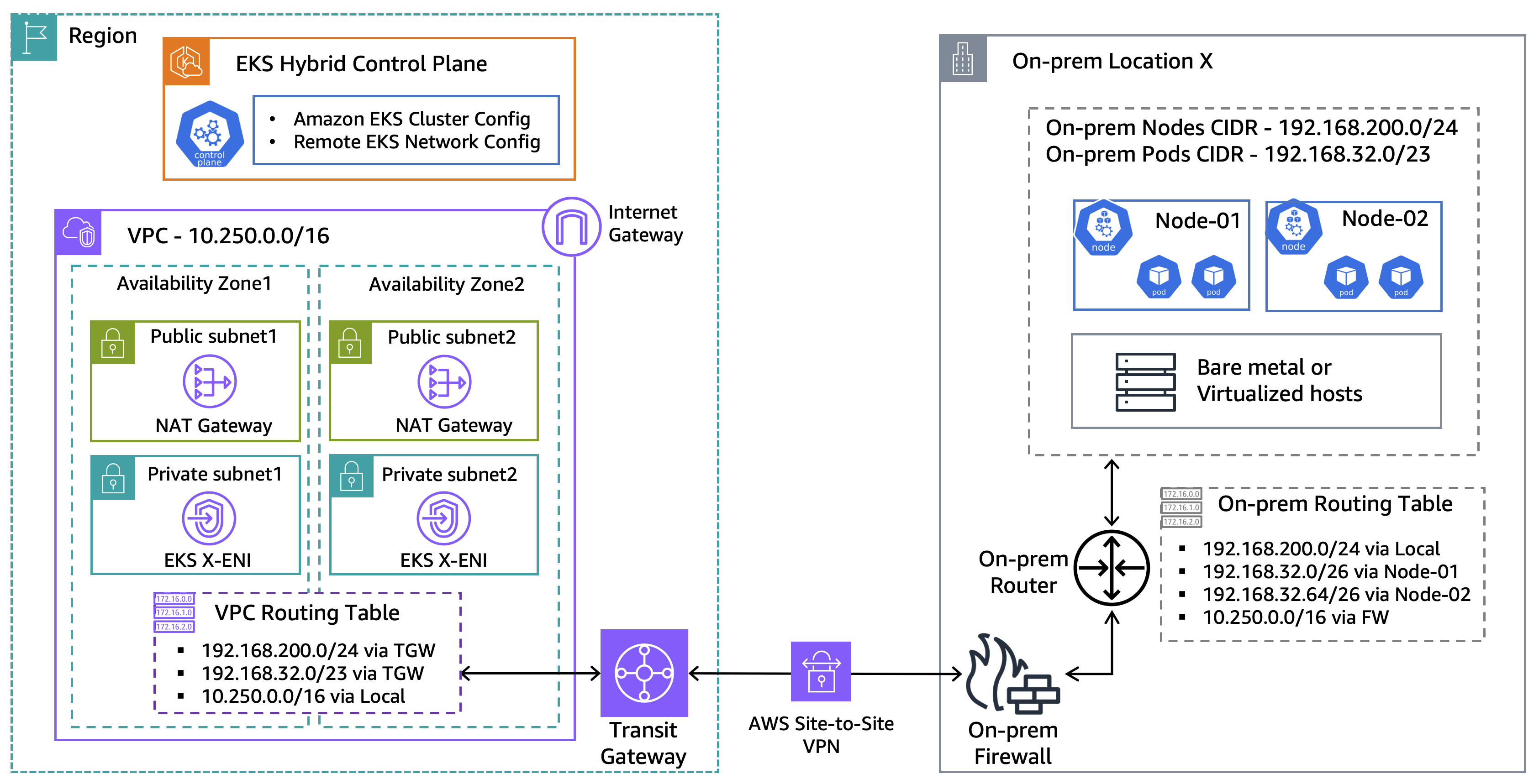
Figure 1: Demo network architecture for EKS Hybrid Nodes
CNI considerations
The Amazon VPC CNI is not compatible with EKS Hybrid Nodes deployments. To make sure that hybrid nodes become operational and ready to handle workloads, you must install a compatible CNI (such as Calico or Cilium). Newly provisioned hybrid nodes in an EKS cluster remain in a NotReady state until a CNI is deployed.
If you are running webhooks on hybrid nodes, then you must make sure that on-premises Pod CIDRs are routable across the entire hybrid network environment. This is essential to allow the Amazon EKS control plane to communicate to the webhook pods running on your hybrid nodes.
However, if you cannot make your on-premises pod CIDRs routable at the local network, then you can alternatively run webhooks on cloud nodes in a mixed mode cluster. Refer to the Amazon EKS documentation for more details on design considerations for webhooks and mixed mode clusters.
There are several techniques you can use to make your on-premises pod CIDRs routable or reachable across the hybrid network, such as BGP routing, static routing, or ARP proxying. This post focuses on how to use BGP and static routing methods to make your on-premises pod CIDRs routable on the on-premises network.
Load balancing considerations
The CNI component is responsible for the in-cluster pod networking. However, a load balancer resource is also needed to enable external access to the microservices running on your hybrid nodes.
For services intended for local on-premises traffic, a load balancer controller such as MetalLB can be deployed. It supports the advertisement of load balancer external IP addresses using either Layer 2 (ARP) or Layer 3 (BGP) mode.
When operating in the Layer 2 mode, MetalLB needs you to reserve an address block from within the node subnet as the load-balancing external IP pool. Then, it automatically chooses one node to respond to ARP requests for a load balancer address allocated from the IP pool. This streamlines the load balancer address advertisement and eliminates the complexity of deploying and managing BGP at the remote or edge locations.
Alternatively, if you are planning to publish the service externally to the Region or to the internet, then we recommend using a cloud-native solution such as AWS Load Balancer Controller. It streamlines load balancer configuration and management by natively integrating with Kubernetes Services type of Load Balancer using Network Load Balancers (NLBs), and Ingress resources through Application Load Balancers (ALBs).
Prerequisites
The following prerequisites are necessary to complete this solution:
- Amazon VPC with two private and two public subnets, across two Availability Zones (AZs).
- Tag the two public subnets with the following format, as the prerequisites for integration with ALBs:
- Key – kubernetes.io/role/elb
- Value – 1
- Deploy an EKS cluster with hybrid nodes – follow this AWS containers post for a detailed walkthrough.
- On-premises compute nodes running a compatible operating system.
- Private connectivity between the on-premises network and Amazon VPC (through VPN or Direct Connect).
- Two routable CIDR blocks for
RemoteNodeNetworkandRemotePodNetwork. - Configure the on-premises firewall and the EKS cluster security group to allow bi-directional communications between the Amazon EKS control plane and remote node and pod CIDRs, as per the networking prerequisites.
- The following tools:
Walkthrough
In this walkthrough, we will set up cluster networking for hybrid nodes by exploring different routing methods, including BGP routing with the Cilium CNI and static routing with the Calico CNI. Next, we will install two load balancer options to the Amazon EKS cluster with hybrid nodes, including an on-premises load balancer example using MetalLB, and an external load balancer solution using the AWS Load Balancer Controller.
BGP routing (Cilium example)
BGP is a recommended solution for enhanced scalability and streamlined route distribution for the on-premises Pod CIDRs. In the following example, we deploy the Cilium CNI and configure the on-premises router as a BGP Route Reflector (RR). This enables the on-premises router to dynamically learn Pod CIDRs through BGP without participating in the data path for intra-cluster communications.
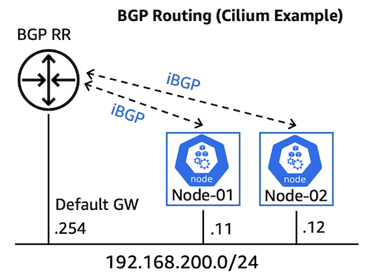
Figure 2: BGP routing for EKS Hybrid Nodes (Cilium example)
- Before we start, the hybrid nodes are currently showing
NotReadybecause this is a newly provisioned cluster.
- First, we create a
cilium-values.yamlfile to specify the whole Pod CIDR range (192.168.32.0/23), with a /26 block size allocated for each node. This CIDR range needs to match theRemotePodNetworkas defined at the EKS cluster provision.
- Next, we deploy Cilium using the preceding values, and make sure to set
bgpControlPlane.enabledtotrue.
- Verify the
cilium-operatorand thecilium-agentrunning on each of the hybrid nodes.
- Apply BGP cluster and peer configurations, such as Autonomous System (AS) numbers, peer-router address, and BGP timer configurations.
- Configure the cluster to advertise Pod CIDRs from each node to the upstream router (BGP RR).
- Finally, apply the BGP configuration at the on-premises router (VyOS example).
- Using Cilium CLI, we can verify the BGP session status at the EKS Hybrid Nodes.
- This can also be confirmed at the on-premises router as we are learning the two /26 Pod CIDRs from the hybrid nodes.
- The status of the hybrid nodes are now changed to
Readywith Cilium CNI installed.
Static routing (Calico example)
For smaller-scale hybrid node deployments, or if using an on-premises gateway lacking BGP support, static routing can be configured to direct traffic for specific Pod CIDRs to their respective nodes. This approach necessitates static assignment of Pod CIDRs to individual nodes. The following steps demonstrate how to achieve this using the Calico CNI.
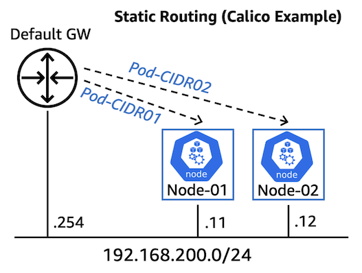
Figure 3: Static routing for EKS Hybrid Nodes (Calico example)
- To allocate per-node based Pod CIDR, we first apply custom labels to each node.
- We create a Calico configuration file that maps specific Pod CIDR block to each node using the matching labels. These CIDRs must fall into the
RemotePodNetworkas defined at the EKS cluster provision stage.
- Now we use Helm to install Calico with the configuration file.
- Two Pod IP pools are automatically created, each containing a /26 CIDR block assigned to a specific node using the custom labels defined previously.
- Lastly, we configure two static routes for the Pod CIDRs at the on-premises router targeting the two nodes, and redistribute them across the hybrid network environment.
On-premises load balancer (MetalLB example)
In the following example, we show how to implement a MetalLB solution in Layer 2 mode on our EKS cluster with hybrid nodes.
- First, we install MetalLB using Helm, and confirm the controller and speakers are in the
Runningstatus.
- Next, we reserve a small address block (192.168.200.201-220) from the node subnet, and assign it for the load balancer external IP pool using the Layer 2 mode. MetalLB now responds to all ARP requests targeting the load balancer addresses allocated from the Layer 2 IP pool, thus eliminating the need of any Layer 3 advertisement.
- We create an Nginx pod for quick testing.
- We then create a load balancer service to expose the Nginx pod using the MetalLB load balancer controller.
- We can see a
LoadBalancerservice is deployed with an external IP (192.168.200.201) automatically assigned from the previously defined Layer 2 IP pool.
- From the on-premises network, we should be able to access the Nginx service through the load balancer’s external IP.
External load balancer (AWS Load Balancer Controller example)
The following section demonstrates how to install the AWS Load Balancer Controller onto our EKS cluster with hybrid nodes. Then, we deploy a demo application using the Kubernetes Ingress through the integration with ALB.
- First, we set up an OpenID Connect (OIDC) provider for our EKS cluster and create an AWS Identity and Access Management (IAM) policy for deploying the AWS Load Balancer Controller.
- Second, we create an Amazon EKS service account for the AWS Load Balancer Controller.
- Next, we install the AWS Load Balancer Controller using Helm and verify the deployment status.
- We use a 2048 game demo application to test the controller. To register pods running on hybrid nodes as remote targets for the ALB, we need to specify
target-typeas IP mode. This is configured using thealb.ingress.kubernetes.io/target-type: ipannotation as defined in the 2048 deployment file under the Ingress section.
- Deploy the demo application using Kubernetes
Ingressthrough the ALB integration.
- We see there are five (replica) pods running across our hybrid nodes, and an ALB is automatically created as the Kubernetes Ingress for publishing the demo application to the internet.
- We can now access the 2048 game through the ALB DNS address, as shown in the following figure.

Figure 4: Accessing the demo app hosted on EKS Hybrid Nodes through ALB
Cleaning up
To remove the demo resources created in the preceding steps, use the following commands:
If the demo environment is no longer needed, then delete the EKS cluster to avoid incurring charges.
Conclusion
In this post, we went through detailed steps for setting up the cluster networking for Amazon EKS Hybrid Nodes. We explored different CNI and load balancing solutions for various use cases and scenarios.
On-premises and edge environments often vary, and you should choose the approach that best fits your networking needs. If it’s possible for your environment, then it’s recommended to use the CNI’s built-in BGP functionality to advertise Pod CIDRs and to use AWS services such as ALB to remove undifferentiated heavy lifting.
To learn more about EKS Hybrid Nodes and apply these techniques to your own environments, see the following resources:
- Amazon EKS Hybrid Nodes user guide
- AWS Blog: A deep dive into Amazon EKS Hybrid Nodes
- AWS re:Post: Deploying Cilium Networking on Amazon EKS Hybrid Nodes
About the author
 Sheng Chen is a Sr. Specialist Solutions Architect at AWS Australia, bringing over 20 years of experience in IT infrastructure, cloud architecture and multi-cloud networking. In his current role, Sheng helps customers accelerate cloud migrations and application modernization by leveraging cloud-native technologies. His recent focus includes Kubernetes, K8s networking, Agentic AI and platform engineering.
 Frank Fan is a Sr. Container Solutions Architect at AWS Australia. As a passionate advocate for application modernization, Frank specializes in containerization and overseeing large-scale migration and modernization initiatives. Frank is a frequent speaker at prominent tech events including AWS reInvent, AWS Summit and Kubernetes Community Day. You can get in touch with Frank via his LinkedIn page, and his presentations are available at his YouTube channel.